Anyway, here are the plans:
Monday, July 28, 2008
Circle Jig: Plans
At the request of a few people, I measured this thing so others could easily replicate it. This is by no means a definitive way of making this jig. The main thing is to make sure the larger circle is bigger than the base of your router and go from there.
Anyway, here are the plans:
 I'm just about finished!
Anyway, here are the plans:
Sunday, July 27, 2008
Circle Jig: Part 5 (Finished!)
After way too much time working on this thing I am finally ready to start cutting some circles! The circle jig is complete. The last step was to drill a hole in the sliding block for the nail which acts as the pivot pin. Drilling the hole was difficult without a drill press. I bought a drill guide but it was totally useless.
After finishing the jig I had to test it out. First, I drilled a 1/8" hole in a piece of scrap MDF for the pivot pin which acts as the center of the circle.

After placing the pivot pin in the center hole, I laid the jig on top and adjusted the radius of the circle until I had the size I wanted. Then I tightened the screw to keep the sliding block in place.
 Next, I turned the router on and plunged the bit into the work piece. Finally, with one hand on the router and the other hand on the jig near the pivot pin to keep everything in place, I used the jig to cut out a circle!
 Easy! Now I can get back to working on my jukebox - it's about time!
Saturday, July 26, 2008
Circle Jig: Part 4
One of the last things to for this jig was to manufacture the sliding mechanism for adjusting the radius of circles I'll be able to cut. I cut a small block out of MDF which fits in the large slot and lays flush on the bottom of the jig. I had to do a bit of sanding to get it to fit in there properly - I didn't want it to be too loose in there - a snug fit works best. As you can see from these two pictures, the block slides up and down the channel on the bottom of the jig.

 With the block in place, I drew some lines on it through the smaller 1/4" opening from the top of the jig so I would know where to place the screw I will use for locking the block in place. It's not exactly centered but it doesn't have to be (although you should aim for that if you decide to build one of these yourself).
 The next step was to drill a hole in the area I just laid out. This will be for the locking mechanism which is just a screw on the top and a tee nut on the bottom.
 Next, I flipped the block over and used a foerstner bit to countersink the tee-nut so it is flush with the bottom (or even a little recessed). I had to tap it in pretty hard with the hammer.
 As you can now see, the screw goes in the tee nut through the top of the jig and locks the sliding block into place. So when I'm using this thing all I have to do is measure the distance from whatever router bit I'm using to the center of the pin and that will be the radius of the circle. Easy!


 This shot from my last post shows the (almost) completed jig. I cut out a handle of sorts to help me slide the block up and down the jig as well as enable me to lock it into place.
 Here is a random shot of some of the supplies I used in case anyone is interested:
 I'm almost done. The final step is just to drill a hole in the block for a #10 nail which will act as the pivot pin. Unfortunately, I don't have a drill press and it is imperative that this hole be exactly perpendicular. Any deviation will throw off the radius of any circles I try to cut! I think I figured out how to drill the hole but that will have to wait until tonight and then I can test it out!

 With the block in place, I drew some lines on it through the smaller 1/4" opening from the top of the jig so I would know where to place the screw I will use for locking the block in place. It's not exactly centered but it doesn't have to be (although you should aim for that if you decide to build one of these yourself).
 The next step was to drill a hole in the area I just laid out. This will be for the locking mechanism which is just a screw on the top and a tee nut on the bottom.
 Next, I flipped the block over and used a foerstner bit to countersink the tee-nut so it is flush with the bottom (or even a little recessed). I had to tap it in pretty hard with the hammer.
 As you can now see, the screw goes in the tee nut through the top of the jig and locks the sliding block into place. So when I'm using this thing all I have to do is measure the distance from whatever router bit I'm using to the center of the pin and that will be the radius of the circle. Easy!

 This shot from my last post shows the (almost) completed jig. I cut out a handle of sorts to help me slide the block up and down the jig as well as enable me to lock it into place.
 Here is a random shot of some of the supplies I used in case anyone is interested:
 I'm almost done. The final step is just to drill a hole in the block for a #10 nail which will act as the pivot pin. Unfortunately, I don't have a drill press and it is imperative that this hole be exactly perpendicular. Any deviation will throw off the radius of any circles I try to cut! I think I figured out how to drill the hole but that will have to wait until tonight and then I can test it out!
Friday, July 25, 2008
Circle Jig: Part 3
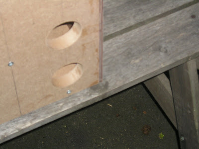
The next step for this jig is to drill holes in the circular section so I can secure the router in place. The placement of these holes depends on the location of the screws on the router's base plate. It was actually pretty easy to do.
First, I removed the plate from the base of my router's plunge base. Then I clamped it into place with come spring clamps. I just eyeballed the location here. Next I drilled three holes all the way through the material for the three screws which will hold the router in place.
 Next, I drilled out around the holes using a foerstner bit - this provides room for the screw heads so the base can lie flush with whatever you are routing. Also, the MDF is considerably thicker than the plastic base plate so I had to drill down about 3/8" in order for the screws to have enough length to poke out of the bottom and grab onto the router. Go slow on this part and remove a little material at a time and check the screw position. When you are satisfied that there is enough of the screw sticking out of the MDF to grab onto the router you can stop drilling down. Make sure not to go too deep. Repeat this for all three holes.
 That's all there is to securing the router in place. It's pretty easy if you have the right tools (isn't everything?). Anyway, here are some shots of the router secured in place as well as a sneak peek of the sliding mechanism for adjusting the diameter of the circles which I will explain next.

 One more step and this thing is finally finished!
First, I removed the plate from the base of my router's plunge base. Then I clamped it into place with come spring clamps. I just eyeballed the location here. Next I drilled three holes all the way through the material for the three screws which will hold the router in place.
 Next, I drilled out around the holes using a foerstner bit - this provides room for the screw heads so the base can lie flush with whatever you are routing. Also, the MDF is considerably thicker than the plastic base plate so I had to drill down about 3/8" in order for the screws to have enough length to poke out of the bottom and grab onto the router. Go slow on this part and remove a little material at a time and check the screw position. When you are satisfied that there is enough of the screw sticking out of the MDF to grab onto the router you can stop drilling down. Make sure not to go too deep. Repeat this for all three holes.
 That's all there is to securing the router in place. It's pretty easy if you have the right tools (isn't everything?). Anyway, here are some shots of the router secured in place as well as a sneak peek of the sliding mechanism for adjusting the diameter of the circles which I will explain next.
 One more step and this thing is finally finished!
Thursday, July 24, 2008
Circle Jig: Part 2
The next step was to cut the 1/4" slot for the smaller panel. This was a bit tricky to set up with my router due to the small surface area of the panel but I managed to figure it out.
 After that was done I glued it to the larger panel. The brown board in the middle is a spacer to make sure the groove stays at 1/4" wide during the glue-up.
 Next, once the glue dried I used my router and a round-over bit to smooth over the edges of the jig (purely for decorative purposes).
 The final steps will be fabricating the center block with the knob and pin which will slid in the groove. Then I'll drill the holes for mounting the router.
Wednesday, July 23, 2008
Circle Jig: Part 1
I've been avoiding this for quite some time but it's now necessary for me to build a circle cutting jig for my router. Tonight I got about 1/2 way finished with it. I am trying to make something similar to what mountain over at BYOAC made.
The first thing I did was lay out the pattern I thought would work.
 Then using a combination of my jigsaw and router with flush cutting bit and a straight edge I cut out the shape. Finally, I cut out a second piece about half the size using my pattern cutting bit.
 This last pic shows how the two pieces will fit together.
 I am going to add a block with a pin sticking out which will slide up and down along the center groove I cut out. The smaller piece will also have a groove cut out but just wide enough for the pin to move up and down. The block will also have a knob on it to tighten the pin into place. The router goes on the circular end with the bit fitting through the center hole. The entire thing will pivot on the pin.
I'm thinking I'll also have to build a makeshift router table at some point too. I'll probably post details of that as well...
Tuesday, July 22, 2008
Front Panel: Even More of the Template
I spent about 2 more hours planning and laying out the front panel tonight. It has been difficult getting the "right" proportions. This thing is going to be extremely tight on the inside! I think I've come up with a suitable layout though. I'm not sure if you can see the lines but here's a shot of the front panel all laid out:
 The trick was to get a somewhat uniform layout and still have room on the front to include everything. The back of the panel is where all of the clutter is going to be because the monitor and volume knob actually take up more surface area back there due to the mounting screws and other stuff. As I get further along you will see what I mean.
The speaker area is going to be a little tight but I'm planning to use one of those long speaker bars that usually plug into an LCD monitor or something. I will also be putting an "audio out" port on the back so if I want to get some really nice sound I'll be able to hook it up to a receiver.
I'm still waiting on the Griffin Powermate to arrive and I don't want to actually cut the front panel until it gets here so I can be sure my measurements are accurate. I haven't been able to find the diameter of the knob. Hopefully that will happen tomorrow.
Monday, July 21, 2008
Front Panel: More of the Template
 Wow was it hot this past weekend! I didn't get much done other than some measuring and planning because I couldn't work on this thing for more than 15 minutes due to the heat. I was at the Yankee game on Saturday and it was miserable (at least they won but I was home on my couch by the time the game was over!).
Anyway, now that I have the general shape of the front panel, it is time to lay out the three openings for the marquee, monitor and the speakers. This is going to be very difficult to cut out since the top opening has two curves which must be precise. The general layout will look something like what you see to the left. The semi-circle in the middle that is not getting cut out is where the volume knob will go.
The usable touchscreen area of the monitor is 11-15/16" wide by 8-15/16" tall. The 11-15/16" dimension will define the width of the side borders which will be 2-1/32" wide each (the width of the panel is 16"). Now I have to decide how thick I want the borders to be on top of the curve, between the marquee and monitor, between the monitor and speakers and between the speakers and the bottom edge to make the overall layout pleasing to the eye.
Once the Griffin Powermate arrives I can measure the knob and add about 3/4" or so around the outside and lay out that section as well. I am anxious to continue working on this thing and I'm really going to push to get the front panel complete this week.
Friday, July 18, 2008
Testing the Monitor
Last night I really wanted to get started with laying out the front panel. All of the dimensions are going to be based on the area of the lit part of the monitor so I had to fire it up - to make some measurements, of course! After I installed the drivers I just hooked it up as a second monitor to my laptop - I can't wipe the smile off of my face.

 I've never played with one of these things before and it is so freaking cool. I was messing around in iTunes and I can see how these things are perfect for jukeboxes. Your finger works just like a mouse and it is quite accurate. I was able to easily control iTunes with just my finger! I'm actually debating now whether I should install a wireless card for Internet access - it would make it easy to get album art and stuff.
Anyway, I got the measurements I needed - 11-15/16" wide by 8-15/16" tall. This is how big the hole on the front panel needs to be. I am going to lay out everything next and begin cutting!
Thursday, July 17, 2008
The Touchscreen Monitor Has Arrived!
Last night when I got home from work I had two packages waiting for me - the 1/8" black plexiglass I will be using for the front of the jukebox and, more importantly, the touchscreen monitor! I ordered it off of eBay for $103 shipped - a very good price, I think.
Anyway, upon opening the box this is what was inside:
 The screen was well protected and shipped in a large box.
 There were a few fingerprints and smudges on the screen which was to be expected but there are no scratches that I could see.
 I do have one problem to deal with though and I'm not sure how I'm going to handle it. The picture below is a close up of the corner of the monitor. The part that I circled is a wire that is attached to the glass which sits about 1/8" off of the top. I want the 1/8" black plexiglass to sit flush with the glass of the monitor but with this wire in the way that is not possible. I'm not sure what I am going to do about this. Worst case scenario is that the monitor won't be flush with the plexiglass but I hope I can think of a better solution.
 The next step is to plug in the monitor to make sure it works but more importantly I want to get the exact dimensions of the screen when it is turned on so I can lay out the front panel.
Tuesday, July 15, 2008
Front Panel: Template
After working on the front template tonight I realized this part is going to take quite a bit of time. I did manage to cut out the general shape of the front in less than an hour though.
First, I traced the shape of the front of the jukebox onto some 1/2" MDF and rough cut it out with my jigsaw staying about 1/8" wide of the line.
 Next, I screwed the panel down to prepare to route the panel to size. I am not worried about leaving holes in the jukebox because the material will eventually be removed (more on that much later).
 After the piece was secured in place I used my router and flush cutting bit to make the 1/2" MDF panel exactly the right size.
 Finally, I removed the newly cut panel.
 Now I'm ready to lay out the hole openings for the marquee, monitor and speakers. Unfortunately, the monitor hasn't arrived in the mail yet and I need that to start. Hopefully I can continue working on this tomorrow...
Monday, July 14, 2008
Slow and Steady
I'd call the first week of work on this thing a success. So far I've cut out the template for the general shape of the jukebox, made the bottom panel and interior spacers and wrapped the front and back panels with two layers of 1/8" hardboard. At this point you can begin to see what the final product will look like.
This week's goals are as follows:
Night 1: New Front Template
The front panel of the jukebox is going to be made out of 1/8" black plexiglass. In order to cut the plexiglass to the proper shape I have to make a template out of 1/2" MDF. Now that I know the final shape of the jukebox I can use my router and a flush cutting bit to make the front template. This template will have three interior holes which must also be cut precise - one for the monitor, one for the marquee and one for the speakers.
Night 2: More of the New Front Template
Realistically, cutting out this template is going to take 2 nights and possibly 3 - there are a lot of tricky cuts and everything must be perfect. On the second night I'm going to focus on cutting out the three holes mentioned above.
Night 3: Cutting the Plexiglass
Finally, after getting the template made, I'll cut the black plexiglass to final dimensions. After the plexiglass is cut, I'll also put a 45 degree bevel on all of the interior edges for decorative purposes. That might be it for this week but I'll keep going if I finish all this stuff early!
Sunday, July 13, 2008
More of the Curved Panel
After flush cutting the curved panel it was time to add another 1/8" layer to the curve to get to the final 1/4" thickness. This process is identical to what I did last night only this time I have a lot more surface to glue to. I can also use my two band clamps to help keep everything nice and flat.
Before starting, I decided to rough up the surface of the hardboard with some 100 grit sandpaper so the glue will have something to grab on to. I'm hoping the glue holds over time but so far so good...

Before starting, I decided to rough up the surface of the hardboard with some 100 grit sandpaper so the glue will have something to grab on to. I'm hoping the glue holds over time but so far so good...


Saturday, July 12, 2008
The Curved Panel: Trim
After letting the glue set overnight now comes the moment of truth... would the curved panel spring back or would the bond from the wood glue be enough to hold it in place? The clamps are off and so far so good!
Now comes the tricky part - removing the excess material that overhangs the edges. Normally this is an easy task with a flush trim bit and a router, however, going over the curve is going to be difficult. I have to clamp the jukebox in place and then go around the curve ever so slightly. The router base will not be laying flat.
Success! Check it out - it is really starting to take shape:


 Tonight I'm going to glue the second 1/8" layer so by tomorrow afternoon the shell should be complete!
Friday, July 11, 2008
The Curved Panel
Today I went to Home Depot and bought some 1/8" hardboard. It is bendable but it clearly wasn't made to be bent. I also picked up some extra spring clamps to help me with the glue-up. They were only $0.99 each!
Once the interior pieces were cut I was able to screw everything together to get the general shape of the jukebox. I'm using screws here because once the glue dries from attaching the curved panel I'll be removing the bottom and the interior spacers.
Next I attached the hardboard panel and I was praying that it would bend along the curve without breaking (or putting a serious amount of tension on it). It seems OK so far...
This forms the sides and top of the jukebox - now we are getting somewhere! I'm actually using two 1/8" sheets so the final thickness of the top and side panels will be 1/4" to give it a little more strength. In order to hold everything in place while the glue dries I can finally use those holes I cut out in the front and back panels last night.


 Not bad. Once the glue dries I'll use my router and flush bit to even everything out and then glue the second layer of 1/8" material giving me a 1/4" thickness on the curved panel.
Subscribe to:
Posts (Atom)
