Thursday, March 17, 2011

Where Was I???

Wow! Has it been 2 years since my last post? I was so close to the finish line and then I just kind of.... stopped. Anyway, life got in the way but I think I'm ready to start this project back up again and finish it off.

I've been tinkering a little and here's a shot of the juke with the screen on and a touchscreen game running:


There's actually not much left to do - the back door has been giving me loads of trouble (it needs to be thin but when I laminate the 1/8" hard board it always warps over time). I keep wasting laminate and that stuff is expensive!

Anyway, I hope to post some more progress sooner rather than later.

Friday, March 6, 2009

The Back Panel V

The next thing I had to do was attach the metal to the inside of the back panel for the magnets to catch on to. This was fairly easy - I laid out corresponding holes to the magnets I installed on the back of the jukebox shell and then used my plunge router to remove some material in the back panel so the metal catches could sit flush. Then I used some two-part epoxy to glue the metal catches in place.

This is what it looked like all clamped up:

I haven't actually tested it yet to see if the panel stays in place like I'm hoping but I will tomorrow.

More later.

Thursday, March 5, 2009

The Back Panel IV

This next part is kind of tricky and I don't even know if it worked yet. I wanted to connect the back panel to the jukebox shell without any visible screws. I'm not even exactly sure why since screws would have made everything much easier. Anyway, I ordered some rare earth magnets from Rockler. They are strong!

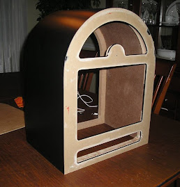
I measured around the outside frame of the back of the jukebox shell and laid out 10 points where I would install magnets. Here is a shot sort of showing how I laid them out:

Here's a close-up of the magnet casing:

I needed to use a 1/2" forstner bit and drill down to precisely the depth of the magnets in order to make them flush. Easier said than done - once you put the magnet in place there is virtually no way to remove it. I ended up drilling down a little too far in some spots - hopefully the magnets will be strong enough anyway.

Each magnet cup (holder?) has a hole in the bottom so it can be screwed into place.

Here is what one of them looks like:

Here is what all of them look like when put in place.

Finally, I put the magnets in there. I cannot get them out so there is no turning back now.

The magnets are a cool idea (at least I think so) but I just hope they end up working like I think they will. It should be easy to remove the back panel by tipping the jukebox forward and going up from underneath assuming the panel locks into place. We shall see...

More later.

Wednesday, March 4, 2009

The Feet!

Here is some exciting news - I finally installed the rubber feet! I bought them at Home Depot for a few dollars and they came with the screws.

Since I do not have a bottom panel the first thing I did was cut out some small triangles out of MDF and glued them in place in the back. I did not have to do this in the front because the panel here is actually 1.5" thick (2 MDF panels).

I just eyeballed the locations, drilled the holes and fastened the feet to the bottom. This may not seem like a big deal but it makes it so much easier to place on the table or wherever to continue working on it.

I also trimmed the t-molding to final length and fixed the slot in the back - it had broken off a little since the slot is so close to the edge (to compensate for the thickness of the back panel). It is solid now and looks great.

More later!

Monday, March 2, 2009

Installing The Volume Knob

Now I'm getting somewhere... I FINALLY cut the hole for the volume knob and got everything installed.

I used a step drill bit and cut out a 7/8" hole where the volume knob goes. As I explained in another post, I am using a Griffin Powermate for the knob and the guts. All that I had to do was drill a hole big enough so the guts of the knob would fit through but I had to be sure it was smaller than the spacer I created. I also had to worry about the knob being dead center (which is harder than it sounds) because this would be the focal point of the entire juke.

Here is a shot of the hole completely drilled out:


After drilling out the hole I had to use a file to remove a little more material to get the guts of the knob to fit properly. The next step was to put the spacer in place and trace it with a pencil so I would know how much of the protective paper I could remove. Once that was done, I used a two part epoxy for plastic to bond the spacer to the front panel.

The epoxy I used set in 6 minutes (less actually) and I was able to remove the clamp fairly quick and install everything. here are some shots without the knob in place:

This is what it looks like with the knob installed.

This last shot I tried to get head on so you could see how I managed to get the knob dead center but the flash was messing everything up. Oh well.

I can't wait to remove the brown protective paper but you should be able to tell what it will look like when I finally do.

Saturday, December 20, 2008

The Computer Installation III

After getting the motherboard and power supply in place, the rest of the components just kind of worked themselves out. This is just a test run (since I have to still cut the hole for the volume knob) but I will use some velcro to secure the speakers in place behind the speaker grill and I wired the power button to the pins on the motherboard (temporarily since it will ultimately be installed in the back panel).

This is a shot of the speaker bar in place from the bottom. You can get a good look here at the support for the shelf as well as the computer fan mounted underneath.

This last shot basically shows what the thing will look like from the front (if you can imagine the protective paper on the Plexiglas peeled off and the marquee in place). The speaker grill is installed and matches the vent on the back as well as the chrome colored t-molding and volume knob.

It looks pretty good!

More later.

Tuesday, November 18, 2008

The Computer Installation II

After installing the monitor and shelf in place, I made sure to get the computer up and running before putting the rest of the components inside.

After that was finished (and I played around for a while), the next step was making sure the motherboard and power supply fit properly. I placed the motherboard on one side (using PCB feet) and the hard drive on the other (using velcro) and tried installing the vertical shelf.

Unfortunately, my initial attempt didn't work - there wasn't enough room for the power supply and the frontx cables I was planning on using weren't long enough to reach to the back panel with the motherboard ports facing to the right. I ended up having to face the motherboard ports down towards the bottom and move the motherboard off center to the right to make room for the power supply.

I was worried initially that since the ports were facing down and the whole thing was off-center that the fan underneath wouldn't keep things cool but boy was I wrong. After leaving it on for at least 6 hours it was cool as the other side of the pillow in there.

Here is the power supply in place:

More later!