Tuesday, October 28, 2008

The Back Panel III

More progress! After getting the 1/8" MDF laminated and rough cut to size I didn't think there was any way that it would turn out nice considering it was chipped and there was glue everywhere. The next step was cutting the panel to its proper size with my router and flush cutting bit.

First, I put some double sided tape around the perimeter of the jukebox shell:

Then, I carefully placed the rough panel on top of the tape making sure that when the overhanging material was removed that there wouldn't be any chip marks showing. The clamps were for added support although they definitely weren't needed - the double stick tape is pretty strong:

Next, I just went around the outside with the router and ended up with the exact shape I wanted! After I had the proper shape, I used a template I had made way back in the beginning of the project for the front panel to cut out the opening for the vent on the top of the back panel (I used double stick tape again). It was easy - the router cuts through the laminate like butter!

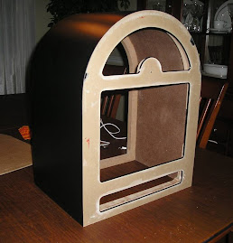
You can still see the glob of glue on top that would have to be removed. After that was finished the last thing I did for the night was drill out the hole for the power button in the center of the small semi-circle. I used my step drill bit and widened the hole to 3/4" diameter.

The button looks great and should match the other aluminum accents on the jukebox (speaker grill, t-molding, etc.). Oh, yeah - I was able to remove the glue using my fingers quite easily. I just rubbed it until it came off from the friction. Check it out (don't mind the dust):

Next up for the back panel is cutting the hole for the I/O panel along the bottom which will mirror the speaker grill on the front panel. Then I will install magnets on the inside so the panel will stay in place but remain removable in case I need to get in there for maintenance.

More later!

Monday, October 27, 2008

The Back Panel II

Now that I had a good idea of what I want the back panel to look like, it was time to start construction. I picked up the laminate from Home Depot (Formica brand) and was happy to see it rolled up in a tube. It shouldn't be a problem to laminate the curved panel! Check it out:

The first thing I did was trace the back of the jukebox shell on to some 1/8" thick MDF and cut out the rough shape. Then, using the rough shape as a template I traced it out on to the laminate and cut it out. I used my jigsaw and it was a mistake - it chipped the laminate like crazy - I probably should have tried scoring it with a utility knife or using some tin snips or something else. After cutting it out I wasn't sure if I left enough overhang around the edges because it was so badly chipped.

Here are the rough panels I cut (MDF and laminate):

I applied a thin coat of contact cement to the MDF and the back of the laminate panel, waited 30 minutes for the glue to dry and then bonded the two surfaces together.

I actually let this cure over night underneath a 3/4" MDF panel and a cinder block.

You can see how imprecise and rough everything is. I also got some contact cement on the good side of the laminate and I was a little worried about getting it off.

What a mess!!! You can see the chipped laminate, the spilled glue and even the permanent marker I used to trace out the shape! Is this going to work out?

Stay tuned!

Sunday, October 26, 2008

The Back Panel

I've been thinking a lot about the back panel of the jukebox and I was able to make some progress on it last night. The cold weather is almost here which will limit my time out in the garage with the tools. It is not nearly as complicated as the front panel, which is good.

I am incorporating the the following:
  • Power button (Vandal)
  • Ventilation
  • 4 USB ports
  • Power cord for power supply
  • Ethernet port (for going online)
  • Headphone jack
  • Audio out ports (for connecting to home theater)
The trickiest part about this panel is that it has to be removable... or at least I need to be able to access the inside for maintenance. I do not want there to be any visible screws on the back panel so I am thinking about using magnets but we will see about that.

The panel will be made out of 1/8" hardboard and covered with Formica laminate. The back panel cannot be any thicker than this or else I will not be able to add t-molding around the top edge while still allowing for the panel to be removed. The layout will mirror the front panel with the power button going where the volume knob is and the vent being where the marquee is. This should give you an idea of how it will look (not even close to scale):

The holes for the ports on the bottom are going to be cut out of a 1mm thick metal panel in a rectangular shape mirroring the speaker cutout on the front panel. The ports on the motherboard are going to be extended to these holes using some cables from frontx.com.

This is a more detailed layout of the I/O panel:

I will start explaining the construction in the next post.

Friday, October 17, 2008

The Speaker Grill

While I am anxiously awaiting the arrival of the laminate I ordered I thought I'd try to get a few smaller things out of the way. I cannot make the back panel or finish the shell without the laminate! The first thing up on the list was figuring out how to cover the speaker opening. I didn't take any specific set of speakers into consideration when I designed this thing - I just thought I'd figure it out when I got that far.... well, now it's time to figure it out.

I decided to use some speaker cloth (available at partsexpress) and some perforated aluminum (available at mcmastercarr) to hide the speaker. The aluminum should tie in nicely to the volume knob and the chrome t-molding I will be wrapping the edges of the case with.

The first thing I did was buy some 1/4" square dowels from Home Depot - I wanted 1/8" but this was the smallest they had. I used the dowels to make a frame slightly smaller than the area routed out behind the speaker opening.

I clamped the cut pieces for about an hour until the glue felt like it would hold.

Once that was finished I sprayed it black just to make sure it wouldn't show at all through the speaker cloth and perforated metal.

Next, I cut out a piece of perforated aluminum to cover the frame.

Finally, I cut out a piece of speaker cloth a bit oversized to wrap the frame. This was a bit tough to figure out but maybe I'm slow. I got some white Elmer's Glue and put a bead around the frame. Then I laid the frame on top of the cloth on a flat surface with a piece of saran wrap underneath so the glue wouldn't stick to the table.

After the glue dried I used a razor to remove the excess material around the edges and I ended up with something like this:

The final step is going to be securing everything behind the Plexiglas in the cabinet. I have a bit more to do before I'm ready to permanently install it but here are a few pictures of what it is going to look like:

I am pretty happy with how everything came out. This was kind of a pain to do - I was expecting it to be an hour tops but I had trouble cutting the perforated metal accurately (third time was a charm).

More later.

Wednesday, October 8, 2008

Gluing the Front Panel to the Shell

Well here we are... after about 2 months of working on the front panel it was finally time to glue it to the shell. This took much longer than I thought it would since I had to remove some extra material around where the monitor opening was so that the monitor would be able to fit in there.

I placed the panel on top and then just used a pencil to outline where I needed to cut. You can see the pencil marks in the next two pictures. I wasn't too worried about making a nice straight line or the cleanest cut since it will all be hidden.

Once I had everything laid out I just used my jigsaw and router (freehand!) to cut as close to the line as possible. The one thing I definitely didn't want to do was cut through the side or something and ruin the shell!

Once the shell was cut properly, I carefully lined everything up and then actually tried installing the monitor. It was a good thing that I did. There were two metal brackets which did not affect the installation into the front panel (I didn't have to account for them) but they would definitely be in the way once the front panel was glued to the shell. I measured the brackets and removed a little bit more material.

Finally, using some wood glue, some clamps and a cinder block I attached the front panel to the shell and let it dry overnight. There's no turning back now!

Lining everything up was tricky. Since there was about 3(!) months between making the shell and cutting the front panel to actually gluing the front panel in place it didn't line up perfect. I think I am splitting hairs though because you can only notice when you rub your finger over the edge. The laminate should go on evenly though (I hope!).

Here are a couple of interior shots so you can see what a mess it is in there. In the bottom left hand corner of the second picture you can see the additional notch I had to cut for the monitor's mounting bracket. I'm really glad I checked before gluing!

Finally, here are some shots of the front panel glued to the shell. It's funny - this thing looks almost exactly like it did 2 months ago!

As soon as the laminate arrives from Home Depot I will glue it to the top/sides - it should be in any day now. In the mean time I am going to start setting up the computer and configuring the software. I think I've turned the corner and I'm past the 1/2 way point now!

More later.

Monday, October 6, 2008

The Volume Knob

I am going to be using a Griffin PowerMate USB knob to control the volume on the jukebox. It will be mounted on the center of the front face in between the touchscreen and the marquee. Here is what it looks like:

I am really only interested in the aluminum knob (and not the base where the blue LED is located) as well as the circuit board on the inside. As you can see from this picture, there is not much to the volume knob and it is actually quite small without the casing:

In order to remove the guts I had to kind of rip apart the knob and I'm going to have to solder a new USB cable to the 4 connector points on the circuit board. I guess I'll cross that bridge when I get to it.

The circuit board is going to fit in the hole I drilled out behind the Plexiglas in a previous post. I am going to have to drill out the Plexiglas a little more for the axle to fit through. In addition, in order to get the knob to lay properly I had to create a 1/8" spacer which I made out of some scrap black Plexiglas.

The first thing I did was find a spare washer that was slightly smaller than the diameter of the volume knob and glue it to some scrap Plexiglas (with the protective paper still on) using some contact cement. Next, I used a hacksaw to cut the Plexiglas as close to the washer as I could and then I sanded it down with some 100 grit sandpaper until the Plexiglas was the same size as the washer. The washer basically acted like a stop for the sandpaper.

Once I was finished sanding, I was able to remove the washer from the Plexiglas with a utility knife. The protective paper came right off. Before calling the spacer "finished" I had to drill a small hole for the volume knob's keyway to fit in otherwise the bottom of the spacer would not be able to lie flush with the top of the circuit board.

You can see why I had to drill the second hole in the next shot. It was easy to lay out - I put the spacer in place before drilling the second hole and then rubbed it back and forth against the keyway - then I just centered my drill bit where the scratch was made and the hole came out perfect.

The next step will be drilling out the Plexiglas on the front panel and using some acrylic glue to bond the spacer to the front. I am going to do a few other things in the mean time though - I need the front of the jukebox to remain flat in order to cut the t-molding slots (among other things). This is what is will look like once it is installed though:

As you can see in the final shot below, once the volume knob is in place, it will be raised by about 1/16" off of the Plexiglas on the front panel which will allow it to turn without rubbing. Perfect!

More later!

Saturday, October 4, 2008

Marquee Template

Not much progress today. I decided that before gluing the front panel to the shell I should make the template for the marquee.... so that's what I did. It wasn't too bad but it definitely didn't come out perfect - good thing it doesn't have to be.

I measured the opening behind the black Plexiglas the best I could and cut out the shape with my router and circle cutting jig. I had to do quite a bit of sanding to get it to fit properly which is why I said it's not perfect.

I added the pencil line after putting the template in place and tracing around the opening. This is the outline of the visible part of the artwork - the only concern is making sure that the artwork is lined up before installing it.

More later.